Erae API SysEx Protocol Reference
The Erae Developer API turns the touch surface into a programmable canvas. From your own software (Max/MSP, TouchDesigner, a Python script, a WebMIDI page), you can:
- Receive raw multi-touch data (X, Y, and pressure) from designated zones of the surface, at a high update rate, without any MIDI note/CC abstraction in the way.
- Draw directly to the LEDs of those zones: clear them, set individual pixels, fill rectangles, and upload full-color images.
- Query each zone's pixel size and the firmware's API protocol version.
Everything travels over USB MIDI System Exclusive (SysEx). This article is the practical wire-level reference. It covers both instruments, Erae 2 and the original Erae Touch (the 2021 model), and calls out exactly where they differ.
Note: This is a developer reference. If you just want to play the instrument, you never need any of this. The API only becomes active for the specific API Zone areas a layout author chooses to place on the surface.
The one concept you need first: API Zones
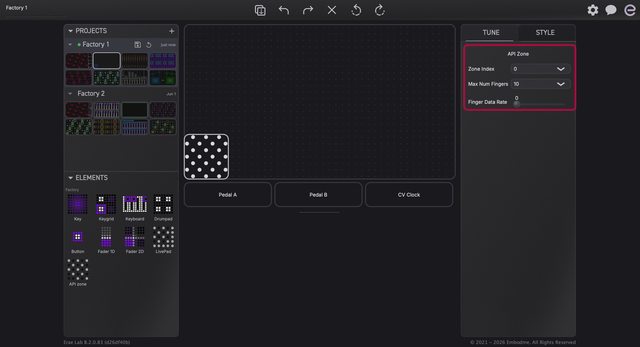
The API does not act on the whole surface. It acts on API Zone elements: rectangular regions you (or a layout author) place in a layout using Erae Lab. Each API Zone has:
- a Zone Index (0-127): the address your software uses to talk to that region,
- a Max Num Fingers setting (0-10): how many simultaneous touches it will report,
- a Finger Data Rate: how often it sends motion updates for a held finger.
Your host software addresses each region by its Zone Index. Drawing to zone 0 lights up the LEDs inside that element; touches inside it stream back tagged with index 0.
Note: Setting the same Zone Index on two elements is undefined: only the first one the firmware registers will receive draw commands. Give every API Zone its own index.
To set up a zone: add an API Zone element to your layout in Erae Lab, set its index and finger parameters, and sync the layout to the device. From then on, that region is under your program's control.
Transport and the SysEx prefix
Erae 2 exposes exactly two USB MIDI ports: the main port and an MPE port. All API messages go over the main port, named Erae 2 MIDI (not the MPE port). Messages flow in both directions on it.
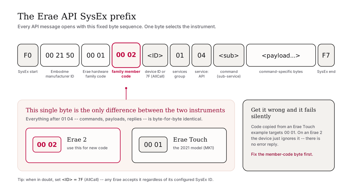
Every API message is a SysEx frame that starts with F0, carries a fixed prefix, and ends with F7. The prefix identifies the manufacturer, the hardware family, and, critically, which instrument you're talking to.
Erae 2 prefix (use this for new code)
F0  00 21 50  00 01  00 02  <ID>  01  04  <sub>  <payload...>  F7
    |          |      |      |     |   |   |
    Embodme    Erae   Erae 2 ID    Svc API Sub-
    manuf ID   family member       grp svc service
| Bytes | Meaning |
|---|---|
F0 | SysEx start |
00 21 50 | Embodme manufacturer ID |
00 01 | Erae hardware family code |
00 02 | Erae 2 family member code |
<ID> | 0x01 (default device ID) or 0x7F (AllCall: broadcast to any Erae) |
01 | Services group |
04 | Service: API |
<sub> | Sub-service ID (the command, see below) |
<payload...> | Command-specific bytes |
F7 | SysEx end |
Erae Touch (MK1) prefix
Identical, with one byte changed: the family member code becomes 00 01:
F0  00 21 50  00 01  00 01  <ID>  01  04  <sub>  <payload...>  F7
                     ^^^^^
                     Erae Touch member code
Warning: The only protocol difference between the two instruments is that member-code byte:
00 02for Erae 2,00 01for Erae Touch. Everything after01 04(command IDs, payloads, replies) is byte-for-byte identical. Code copied from an old Erae Touch example will fail silently on an Erae 2 (and vice versa) until you fix that byte. There is no error reply; the device just ignores the message.
Tip: When in doubt, use AllCall (
0x7F) for the<ID>byte. The device accepts it regardless of its configured SysEx ID, so you don't have to know or match the device's ID.
The command set
The <sub> byte after 01 04 selects the command:
| Sub | Command | Direction | Notes |
|---|---|---|---|
0x01 | StartFingerDataStreaming | host -> device | Turns the stream on |
0x02 | EndFingerDataStreaming | host -> device | Turns the stream off |
0x10 | ZoneBoundaryRequest | host -> device | Ask a zone's pixel size |
0x20 | Clear | host -> device | Blank a zone |
0x21 | SetPixel | host -> device | One LED |
0x22 | DrawRectangle | host -> device | Filled rectangle |
0x23 | DrawImage | host -> device | Full-color bitmap |
0x7F | VersionRequest | host -> device | Erae 2 only: ask the API version |
The examples below use the Erae 2 prefix and AllCall ID. Swap in 00 01 for Erae Touch, and drop VersionRequest (Erae Touch does not answer it).
Start (and stop) the stream
Nothing comes back from the device until you turn the stream on. StartFingerDataStreaming (0x01) enables both the finger data and every reply (zone boundary, version). This is global to the device, not per-zone.
F0 <prefix> 01 <prefix data: 0..16 bytes> F7
The optional prefix data (0-16 bytes, your choice, e.g. four ASCII characters) is echoed verbatim at the start of every message the device sends back. Use it to tag your session so you can tell your replies apart from another host's if several Erae devices share the same USB bus.
Example: start streaming with the tag "jhhl" (6A 68 68 6C):
F0 00 21 50 00 01 00 02 7F 01 04 01 6A 68 68 6C F7
To stop, send EndFingerDataStreaming (0x02) with no payload:
F0 00 21 50 00 01 00 02 7F 01 04 02 F7
Warning: The prefix must be 16 bytes or fewer. If you send more than 16, streaming simply does not turn on: there is no error, and the device stays silent. If "start streaming" seems to do nothing, check your prefix length first.
Always send EndFingerDataStreaming when your host disconnects, so the device isn't left streaming into nothing.
Receiving touches: the Finger Stream
Once streaming is on, every active touch inside an API Zone produces a Finger Stream message, at the zone's configured Finger Data Rate. Multiple zones share one stream and are told apart by their zone index.
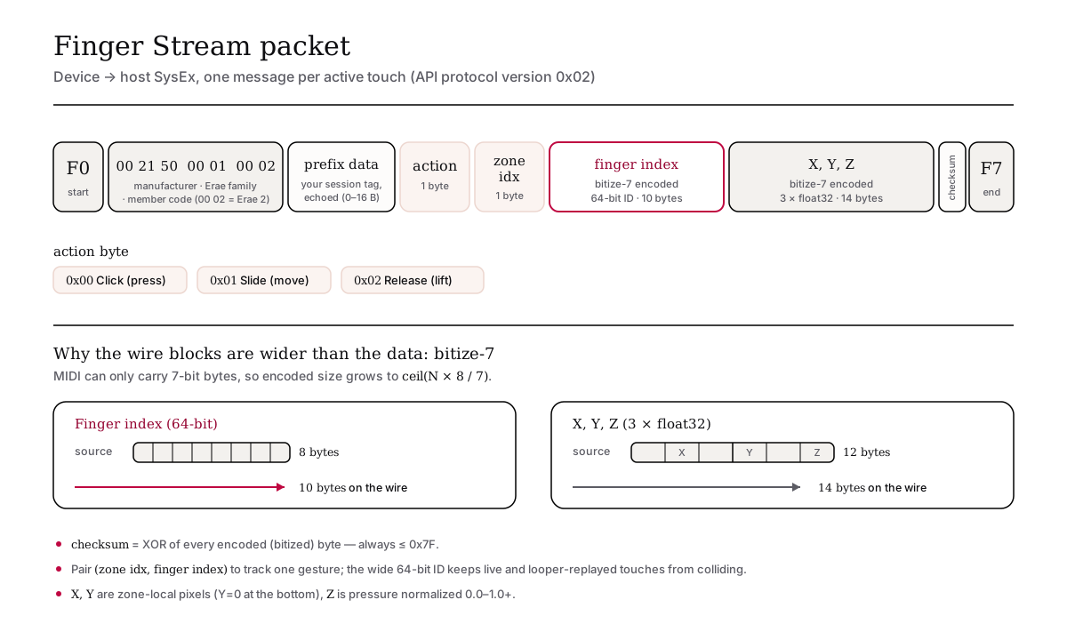
F0  <prefix>  <prefix data>  <action>  <zoneIdx>
    <bitized fingerIdx (64-bit)>       <- 10 bytes on the wire
    <bitized X, Y, Z (3 x float32)>    <- 14 bytes on the wire
    <checksum>  F7
| Field | Meaning |
|---|---|
action | 0x00 = Click (press), 0x01 = Slide (move), 0x02 = Release (lift) |
zoneIdx | Which API Zone the touch is in |
fingerIdx | A 64-bit ID that stays constant for the life of one touch |
X, Y, Z | Zone-local position (pixels) and pressure (Z, normalized 0.0-1.0+) |
checksum | Integrity byte |
The X/Y/Z values arrive bitize-7 encoded (explained below). Reassemble per-finger gestures by pairing (zoneIdx, fingerIdx), and treat a Release as the end of that gesture.
If you're upgrading from an old Erae Touch integration
The Finger Stream body changed. Older firmware (Erae Touch v1.1.2 and earlier) packed the action and a 4-bit finger index into a single byte, with no separate finger-index block. Current firmware (v1.1.3 and later, on both instruments) sends the action as its own byte followed by a dedicated 64-bit finger-index block.
The wider ID was needed so that live touches and looper-replayed gestures (which get random 64-bit IDs) never collide on the same zone. A parser written for the old 4-bit format will misread every message from a current-firmware device. If your old code chops the finger index out of the first byte, that's the part to rewrite.
Note: This body change did not bump the API version number, so you can't tell the two formats apart by version alone. Use
VersionRequestto confirm you're talking to a current-firmware device (see below), and update your parser to the 64-bit body.
Drawing to the surface
The Erae surface is a 42-wide x 24-tall LED grid (1008 LEDs). Inside an API Zone, coordinates are zone-local: (0, 0) is one corner, (width-1, height-1) the opposite corner. Query the exact width and height with ZoneBoundaryRequest.
Colors are 7-bit
Each color component (R, G, B) is a 7-bit value, 0x00-0x7F. The device shifts it up internally, so:
7F 7F 7F= full white7F 00 00= pure red00 00 00= black (off)
Warning: Do not send 8-bit color values (
0..255). MIDI forbids bytes with the high bit set, so0xFFcan't even travel in a SysEx frame. Treat0x7Fas your maximum for every channel.
Clear a zone (0x20)
Blanks the whole zone to black:
F0 00 21 50 00 01 00 02 7F 01 04 20 <zoneIdx> F7
Set one pixel (0x21)
F0 <prefix> 21 <zoneIdx> <x> <y> <R> <G> <B> F7
Example: light pixel (3, 5) red in zone 0:
F0 00 21 50 00 01 00 02 7F 01 04 21 00 03 05 7F 00 00 F7
Out-of-range pixels are silently ignored.
Fill a rectangle (0x22)
F0 <prefix> 22 <zoneIdx> <x> <y> <w> <h> <R> <G> <B> F7
The rectangle is clipped to the zone edges. If x or y is already outside the zone, it's a no-op.
Upload an image (0x23)
DrawImage paints an arbitrary w x h color bitmap. Pixels are read row by row, left to right, top to bottom. Each pixel is three RGB bytes. The pixel data is bitize-7 encoded and followed by a one-byte checksum:
F0 <prefix> 23 <zoneIdx> <x> <y> <w> <h> <bitized RGB...> <chksum> F7
The firmware silently drops the whole image if any of these don't line up:
- the decoded size isn't a whole number of pixels (a multiple of 3),
- the decoded size doesn't equal exactly
w * h * 3, - the image is larger than the surface (
w * h > 1008), - the checksum doesn't match.
Warning:
DrawImageis SysEx-only on both instruments. There is no faster alternative path for it.
The Y-axis flip: the mistake everyone makes once
This is the single most common integration bug, so it gets its own section.
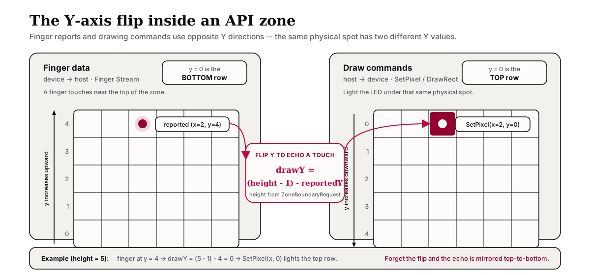
Finger reports and drawing commands use opposite Y directions, and always have; the firmware keeps this behavior for backward compatibility:
| Stream | Direction | y = 0 means |
|---|---|---|
| Finger data (device -> host) | Bottom-origin | the bottom row of the zone |
| Drawing commands (host -> device) | Top-origin | the top row of the zone |
So if a finger is reported at (x, y) and you want to light the LED directly under it, you must flip Y:
drawY = (height - 1) - reportedY
Then call SetPixel(x, drawY, color). Forget the flip and your visual feedback appears mirrored top-to-bottom from the finger. (height is the zone height from ZoneBoundaryRequest.)
Bitize-7 encoding (for image and finger data)
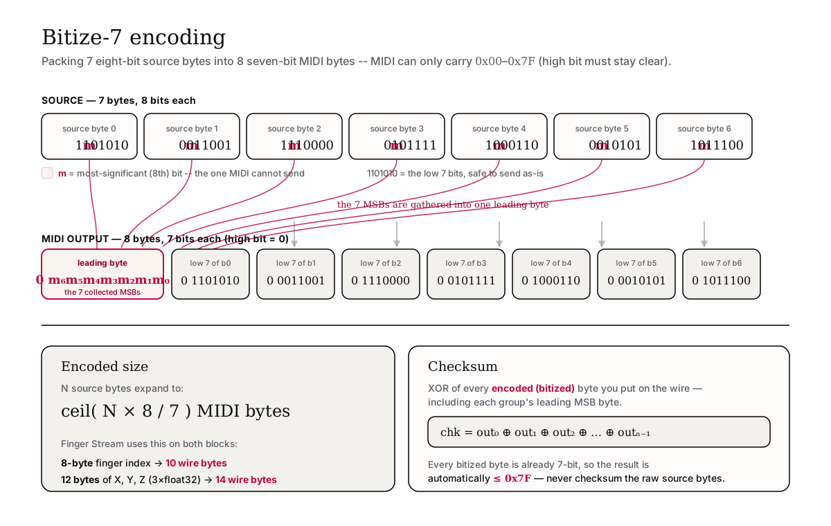
MIDI can only carry bytes 0x00-0x7F: the high bit must stay clear. Raw RGB and float data don't obey that, so the Erae uses a small packing scheme called bitize-7 for DrawImage payloads and the Finger Stream coordinates.
The rule: every 7 source bytes become 8 MIDI bytes. The first of the 8 carries the seven high bits (the ones MIDI can't send) of the following 7 bytes; each of the next 7 bytes carries the low 7 bits of one source byte.
The encoded size of N bytes is ceil(N * 8 / 7). That's why the 8-byte finger index becomes 10 wire bytes, and the 12 bytes of X/Y/Z become 14.
The checksum gotcha
For DrawImage, the checksum is the XOR of every byte you put on the wire: that is, the bitized payload, including each group's leading MSB byte. Because every bitized byte is already 7-bit, the result is automatically <= 0x7F.
Warning: Do not checksum the original RGB source bytes. That accidentally works for dim images (all components below
0x80) but fails for any bright pixel, and the firmware silently drops the image on a mismatch. Checksum the bytes you send, not the bytes you started with.
You don't have to write this yourself. Embodme publishes a Python reference that implements the packer, the checksum, and image upload; see the erae_api_sysex repository (run_erae_api.py). It also ships the full Erae_API_V2.pdf specification.
Querying the device
Zone size: ZoneBoundaryRequest (0x10)
Ask how many pixels wide and tall a zone is:
F0 <prefix> 10 <zoneIdx> F7
The device replies (asynchronously) with:
F0 <prefix> <prefix data> 7F 01 <zoneIdx> <width> <height> F7
If no API Zone with that index exists, width and height both come back as 0x7F. Streaming must be on or you'll get no reply at all.
API version: VersionRequest (0x7F, Erae 2 only)
F0 <Erae 2 prefix> 7F <prefix data: 0..16 bytes> F7
Reply:
F0 <Erae 2 prefix> <prefix data> 7F 02 <apiVersion> F7
apiVersion is currently 0x02. Any reply at all means you're talking to a current-firmware device that emits the 64-bit Finger Stream body described above. Erae Touch, and Erae 2 firmware v1.1.2 or older, do not answer this request, so no reply means "assume the older format, or update the firmware."
Note:
VersionRequestis your version-probe. Since the Finger Stream body changed without a version bump, treat "answers VersionRequest" as the signal that the current 64-bit body is in use.
A typical session, start to finish
- Open the
Erae 2 MIDIinput and output ports. - Send StartFingerDataStreaming with a short prefix tag (e.g. four ASCII bytes).
- Send VersionRequest and confirm the reply (
0x02on Erae 2). No reply = older/other device. - For each zone you care about, send ZoneBoundaryRequest and cache the
(width, height). - Render: Clear, then SetPixel / DrawRectangle / DrawImage. Pace your draws: back-to-back full-surface images can outrun what USB MIDI can deliver and get dropped.
- Process incoming Finger Stream messages, keyed by
(zoneIdx, fingerIdx), and remember the Y-axis flip when you echo touches with LEDs. - Send EndFingerDataStreaming on disconnect.
Limits and silent-failure conditions
The API almost never returns an error: it just ignores what it can't process. Keep this table handy when something "does nothing":
| Condition | What happens |
|---|---|
| Zone index doesn't match any placed API Zone | Command silently dropped |
| Zone index above 127 | Silently dropped (wire range is 0-127) |
x / y outside the zone | Pixel dropped; rectangle/image clipped to the zone |
Color byte above 0x7F | Rejected by MIDI framing; never send 8-bit color |
DrawImage checksum or size mismatch | Whole image silently dropped |
DrawImage bigger than the surface (w * h > 1008) | Silently dropped |
| Start-stream prefix longer than 16 bytes | Streaming does not turn on |
| Replies requested while streaming is off | No reply is sent |
| Two API Zones share one index | Only the first handles draw commands (undefined, avoid) |
For continuous rendering, pace your traffic: a full 1008-pixel image is roughly 3.5 KB on the wire, and the finger stream shares the same USB MIDI cable. If you're drawing heavily, lower the zone's Finger Data Rate (in Erae Lab) so touch updates don't compete with your draws.
Where to go next
- The authoritative, exhaustive byte-level reference is the Erae 2 Manual, Appendix D: Developer API. It includes every payload table, worked encoding examples, and the full error matrix. This article summarizes it for day-to-day use.
- The
erae_api_sysexPython reference is the fastest way to get a working integration: clone it, runrun_erae_api.py, and adapt from there. - To place and configure API Zones in a layout, see the Erae Lab Overview.