
Erae manual
Getting Started
Read this first
Welcome,
Thank you for choosing Erae!
Welcome to a new realm of creativity and expression. Erae is a cutting-edge, touch-sensitive controller and looper designed to seamlessly adapt to your musical journey. We’re excited to see it become the heart of your studio.
What’s in the box
Erae 2 controller
65W US / EU /CN / UK /JP Power supply USB type-C connector
1x Fabric Skin (already mounted on product)
8GB SD card
2x 2m USB type C cables
2x MIDI TRS to DIN adapter
Safety Instructions
Protect properly your Erae during transport and storage, avoiding pressure and friction against the sensors surface as this could de-calibrate and/or permanently damage the built-in array of 16,000 Force Sensors.
Do not use any detergents to clean the skin, as they can damage the coating. Instead, gently clean it with a damp
sponge or a soft white cloth using only water.
Make sure to use the provided 65W power supply adapter for an adequate power source of your Erae 2.
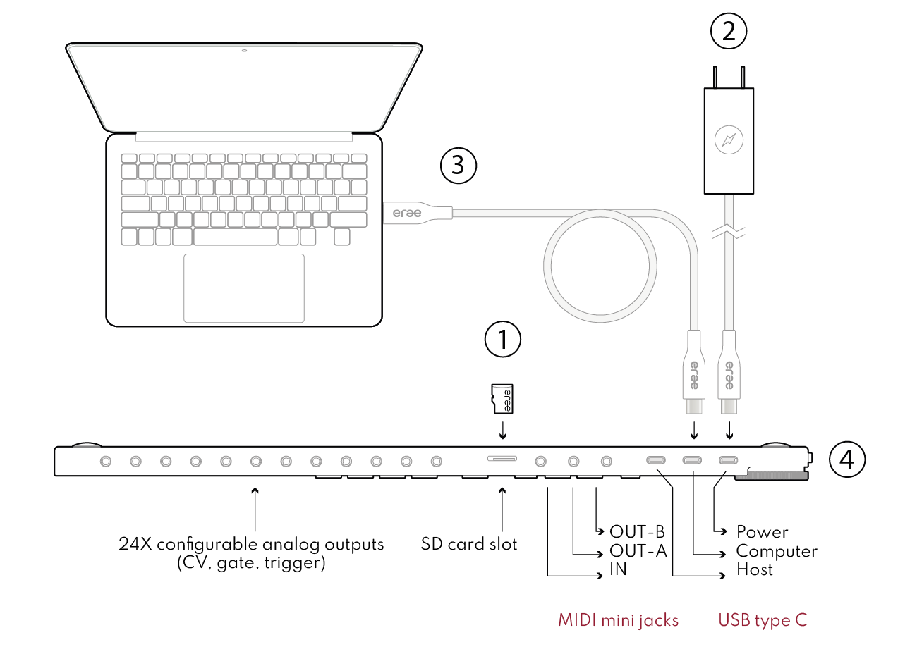
Powering Your Erae
1. Insert the SD card into the slot.
2. Connect the provided 65W power supply to the Erae via the USB port on the right side to enable 100% brightness. Alternatively, the “Computer” USB connector can power your Erae at up to 25% brightness.
3. Connect the Erae to your device.
4. Flip the switch to turn it on!
Stay updated
Download Erae Lab
Visit the download section of the Embodme website to get the companion software Erae Lab. Use it to customize your device and adjust its settings effortlessly.
Update the Firmware
To get started, update your Erae 2 firmware by opening Erae Lab and clicking the “Update Firmware” button when your device is connected. Regular updates ensure you always have access to the latest features and improvements!
More informations on updating your Erae 2 are listed here at https://embodme.freshdesk.com/support/solutions/articles/80001165398-update-your-erae2-firmware
Support
If you need assistance, please visit the forum and FAQ section on our website under Support. For specific troubleshooting help, don’t hesitate to contact us at support@embodme.com — we’re here to assist you.
Getting Started
Erae Glossary
Welcome to the Erae world! Here's a quick guide to the key terms you'll encounter:
- The Lab: Erae's companion software, designed to configure your device in countless ways. In the Lab, you can manage your projects and layouts
- Element: The basic building blocks for creating layouts. Examples include keyboards, drum pads, and faders. A full list of elements can be found in the Elements section.
- Layout: An arrangement of elements on the playing surface. Layouts can be customized with "tune" and "style" settings in the Lab. You can also adjust "tune" settings directly on the device. Both "tune" and "style" parameters are layout-specific, meaning they are saved and edited within their individual layouts.
- Loop: A repeating sequence of MIDI and/or CV events, such as notes, chords, or rhythms. Loops can be recorded in real time, then saved and edited as "patterns."
- Project: A file that can contain up to 8 layouts. Erae's SD card can store up to 8 projects, allowing you to manage and organize your work efficiently.
Getting Started
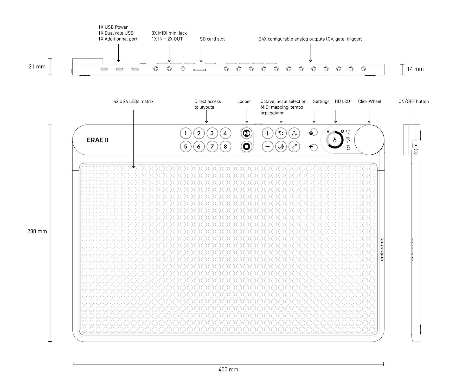
Global description
Playing Surface
The Erae features a built-in array of 16,000 force sensors and 1,000 RGB LEDs, paired with the powerful Erae Lab configuration software. This combination enables limitless customization, supporting up to 8 layouts per project and 8 projects stored on the included SD card. With Erae Lab, you can design your pad to suit your needs by incorporating elements like sliders, 2D sliders, keygrids (isomorphic layouts), or keyboards. The device also includes 8 factory layouts, showcasing its versatile possibilities. Note that many layouts are routed across various channels, with some designed specifically for MIDI Polyphonic Expression (MPE).
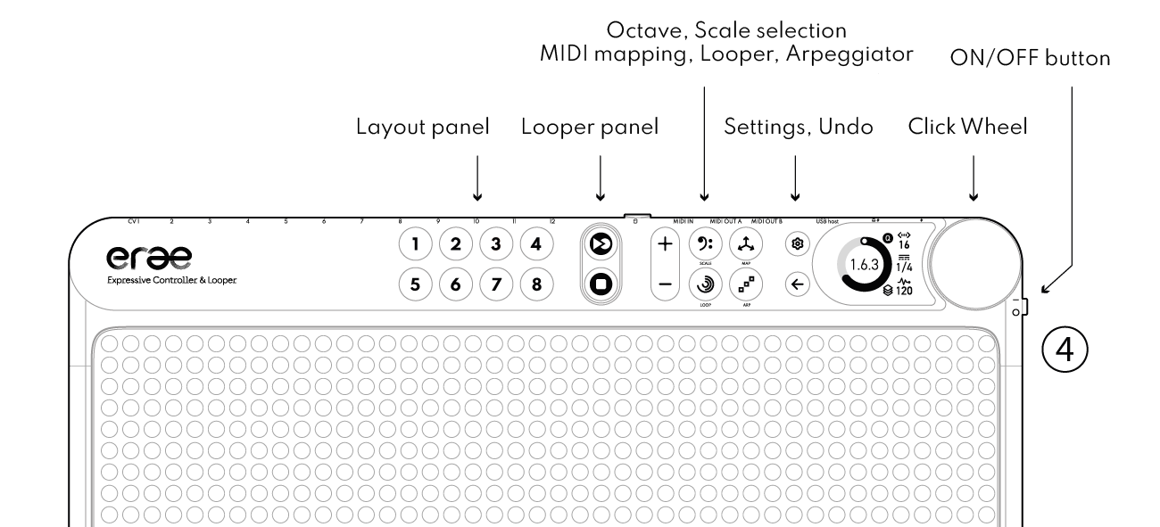
Bouton Panel
Individuel boutons enable directs access to:
- Layouts (1 to 8)
- Looper section
- Octave up & down
- Scale, Mapping, Loop and Arpeggiator
- Settings and Undo
Screen and Click-wheel
Easily navigate and adjust parameters directly on the device using the click-wheel and screen interface. Most parameters on the screen's UI can be navigated by rotating the wheel and selected with a click.
I/O
From left to right (top view point of view), Erae 2 features:
- 12 dual jack outputs, with outputs 11 and 12 also functioning as footswitch pedal inputs.
- One SD card reader supporting up to 8 projects.
- One MIDI input and two MIDI outputs.
- One USB Host port to control USB-compatible synths or receive MIDI from other controllers.
- One USB Device port to send MIDI to a computer.
- One USB port dedicated to the power supply.
Getting Started
Navigation on the front panel
Layouts
Each button, numbered from 1 to 8, corresponds to a specific layout. When you press a button, Erae displays the associated layout, allowing you to play it!
Octave selection
Buttons allow you to change the current octave of the pitched element (keygrid, keyboard, drumpad, note) you touched last.
Scale
To adjust the scale of pitched elements, follow these steps:
The Scale menu consists of three columns:
- Scale Mode (e.g., Major, Melodic Minor, Harmonic Minor, etc.)
- Root Note
- Octave (range: [-2; 8])

Mapping
Touch the mapping mode button to change the output routing, MIDI channel, Control Change (CC’s), de/active MPE, expressive parameters (pitch bend, pressure, etc.) and more.
Remember the menu affects the last touched element.

To edit Mapping elements, navigate through the menu and hover the element you wish to modify. Click and rotate the wheel to make changes. Certain parameters have simple on/off states that can be toggled, while others allow fine-tuning within a [0–100] scale.
NB : These mode parameters can be edited from the Lab or from the Erae.
Arpeggiator
The Arpeggiator is triggered on all pitched elements (Keygrids, Keyboards, Drumpads, Buttons and Notes) once you click the arpeggiator button. First select one pitched element by touching it before hitting the arpeggiator button. The arpeggiator has four parameters:
- Rate - Default: ¼, Range [1/32; 1/1], last value is Pressure, meaning the ARP rate gets faster as you press harder
- Style - Default: Up, Values: Up, Down, Up & Down, Random
- Octave - The range across which spans the Arpeggiator - Default value is 1, Range: [0;8]
- Pressure - Finger pressure controls the arpeggiated notes velocities
Getting Started
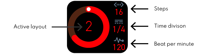
Looper
The looper serves as the default screen for all layouts. It displays time with a red circle expanding over a grey background. In this initial version, the looper allows you to adjust three parameters:
- The number of steps: Default value: 16 steps, range: [0;64]
- The time division: Default value: ¼, range [Off; 1]
Nb: Time division acts like quantisation, set to Off, is similar to no quantisation. - The - Beat Per Minute - BPM can be set here for all layouts/loops.
Looping gestures
The Erae looper records gestures (x,y,z touch data) and not MIDI nor CV data.
This means you can keep looping while transposing octaves, changing scales and changing mapping.
Looper bindings
Typical workflow example

Advanced functions
Layouts and Elements on the playing surface
Elements
The playing surface is where interactive elements come to life, enabling you to engage with and customize your performance. These elements may include:
- Keyboards/keygrids/drumpads: Assign and play notes, beats, or patterns.
- Notes: Trigger sounds or effects with pressure-sensitive touch.
- Sliders: Adjust parameters dynamically by sliding your fingers.
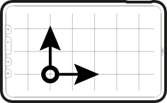
- 2D Sliders: Manipulate up to three parameters simultaneously by moving across the surface.
- Buttons: Switch between modes, toggle effects, or activate features.
Each element is crafted for intuitive interaction, enriching your creative experience. As the fundamental components of all layouts, elements can be arranged and customized within a layout using the Erae Lab. A layout can consist of one or multiple elements, which can be positioned, duplicated, edited, or removed as needed in the Erae Lab.
Keygrid
Keygrids consist of rectangular cells arranged in a grid. Horizontally, the cells are spaced by intervals such as a semitone, a tone, or larger steps, while vertically, they are separated by intervals like a fourth (or greater, adjustable using the line offset attribute, similar to string instruments). The chosen scale determines the precise interval relationships between the rows and columns.
By default, every note on the Keygrid is in the key of C major. Two joint keys on one same line will be separated by one degree of the same scale. In this C Maj example, the root note is C. Moving to the right, each key is the next note in the C major scale. Moving upward, each key is a fourth higher. Again, the note interval between lines can be adjusted in the Lab with the Line Offset.
Scales
Changing scales adjusts the arrangement of note intervals, but the root note, third, and fifth remain highlighted. These highlights and their styles can be customized in the Lab.
Chromatic keygrid
To play chromatically on the keygrid, enable the "Show Offscale" option in the Lab's scale settings menu. Disabling this option will fold the keygrid, showing only the notes within the selected key. By default, notes outside the key are displayed in grey, but you can personalize their appearance in the Lab.
Keyboard
Keys are replicas of traditional keyboards. There are many original ways to represent black and white keys, play around with the Style section in the Lab and find out what works best for you.
Scales
You can highlight in-scale notes to visualize various scales (such as Major, Minor, or Blues), simplifying the process of learning and playing.
Buttons
Buttons trigger notes with selected pitch on a selected channel. They can be used for launching clips on Ableton Live or triggering a button on a hardware synth. They can also be used as switches, with distinct on/off states, by setting the Latched option to on in the Lab.
1D Fader
Sliders provide continuous variation along one dimension, between two defined values, using a specific MIDI channel and Control Change. They can be mapped to both control changes and control voltages (CV), even simultaneously if required. Their value range can be customized in the Lab. By default, sliders are set to the mid-range position, but their initial Y value can also be adjusted in the Lab. You can change the color of their edges, background and level bar in the Lab. (See Style section)
2D Fader
2D sliders enable you to control up to three CCs and/or CVs with a single finger, offering intuitive X/Y/Z movement and visual feedback. You can adjust their value range and initial settings in the Lab, as well as customize the color of their edges, background, and level bar for a personalized look.
Ableton Live Controller
This Launchpad element strips down to the essential : launching Ableton clips, soloing and muting up to 10 tracks.
API Zone
The Erae API is a custom sysex library with messages enabling you to take full control of the Erae point detection and LEDs states.
Advanced functions
Polyphonic Expression Controller (MPE)
Erae 2 is a MIDI Polyphonic Expression Controller (MPE), which is a relatively new standard for expressive electronic music performance. It enhances MIDI by allowing each note played to be controlled independently on its own MIDI channel. This enables expressive features such as pitch bends, vibrato, and dynamics for individual notes in a chord, rather than applying these effects uniformly to all notes.
All pitched elements (such as keygrids, keyboards, and drum pads) can operate in MPE mode by enabling the MPE button either in the Erae Mapping section or the Lab’ Tune section.
MPE in Ableton Live
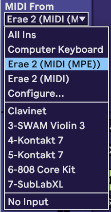
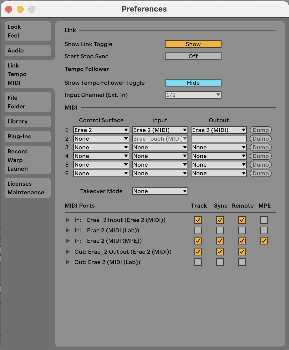
First, make sure your Erae 2 is connected and Erae 2 (MIDI (MPE)) toggled on.
Then, route your Erae 2 (MIDI(MPE)) in the “MIDI from” In/Out Section in Ableton Live. Enabling “Remote” will enable you to map control changes (CCs).
MPE in Logic Pro
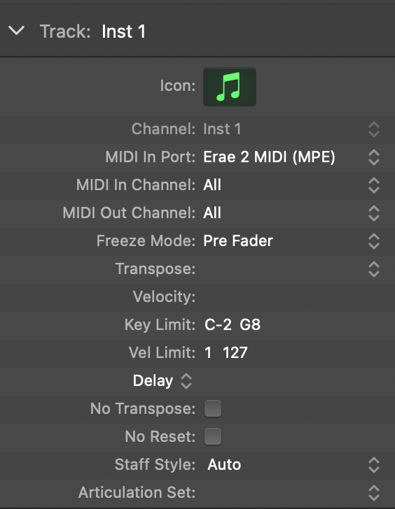
Make sure your Erae 2 is connected and Erae 2 (MIDI (MPE)) selected in the MIDI in Port section in Logic Pro. Also, make sure you are using a compatible MPE AU-instrument!
MPE in Cubase
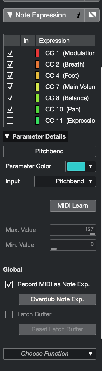
Go in studio > studio setup. Once the window is open, clique on « add device » and select « note expression input device » In midi input, select « Erae 2 Midi (MPE), then select « note expression » in the inspector of your track

Select the desired expressive dimensions or CCs, then click on "Parameter Details" to assign them.
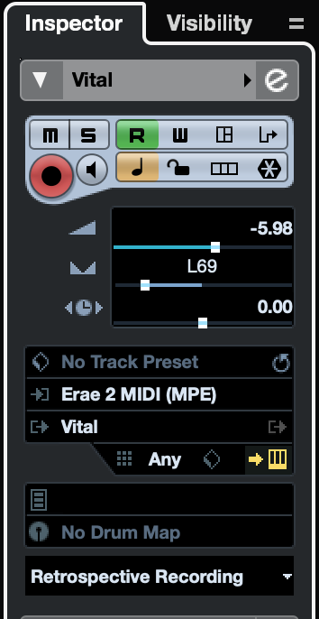
Finally, select in your midi inputs « Erae 2 Midi Input » in your track inspector and set the channels to « any ».
Advanced functions
Settings
Let’s dive into Erae’s setting section, where you will find how to save and load projects, adjust global settings such as the overall LED brightness, tempo, I/O routing and more.
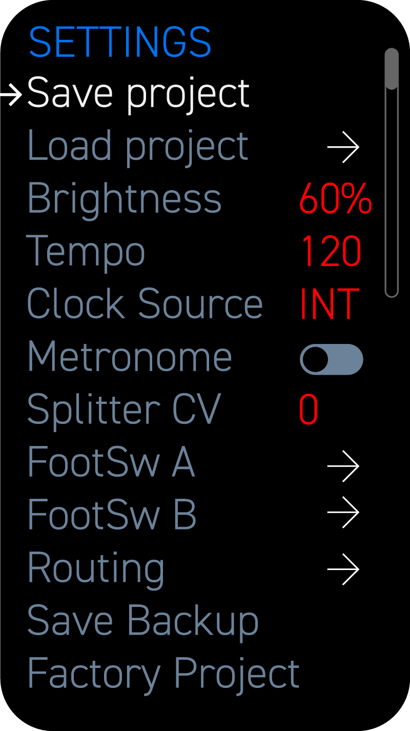
Save Project
Click once to save your project. Note that it will be saved in the current project location, which can be specified in the Load Project parameter.
Load Project
Single-click to cycle through the 8 available projects. Click on a selected project to load it. Use the undo button to return to the Settings menu.
Brightness
The value [0–100%] allows you to adjust the overall LED brightness of the Erae. When powered solely via a USB-C connection to a USB device, brightness is limited to a maximum of 30%.
Tempo
Set your BPM
Clock source
- INT: Internal clock of the Erae 2.
- USB-dev: Clock received via the USB device port.
- MIDI: Clock received through the MIDI IN port (note: the clock will not transmit through the MIDI OUT ports).
Metronome
Activating the metronome enables the Erae's internal click sound during playback or recording with the looper.
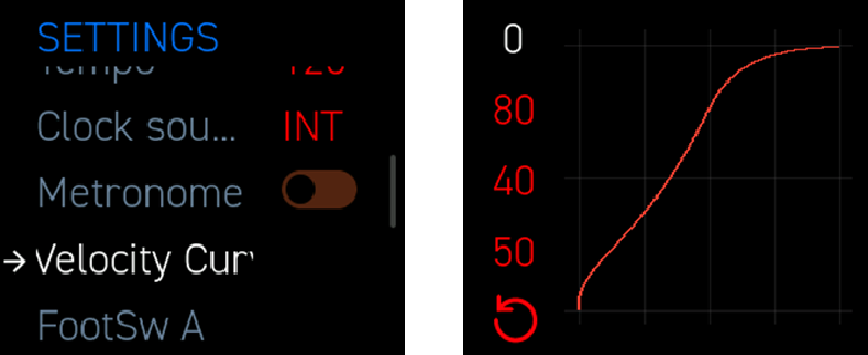
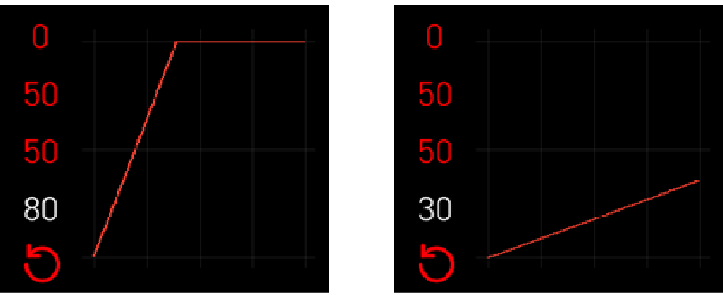
Velocity Curve
The velocity curve allows users to customize velocity response using a configurable curve within the Erae.
How to Access:
- Press [SETTINGS]
- Navigate to Velocity Curve and press the encoder
- Adjust the curve in real-time while playing to instantly see the effect on velocity/pressure
Parameters:
● THRESHOLD : Defines the minimum input forcerequired to register velocity.
○ Higher values filter out lighttouches, requiring firmer pressure.
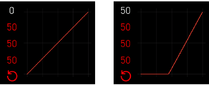
● DRIVE : Pushes values toward the extremesof the curve.
○ Higher drive increases contrast between soft and hard hits.
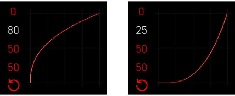
● COMPRESSION / AMPLIFICATION : Adjusts the curve’sshape by boosting or compressing values around the midpoint.
○ Expands or limits the range ofsofter/louder inputs for better dynamic control.
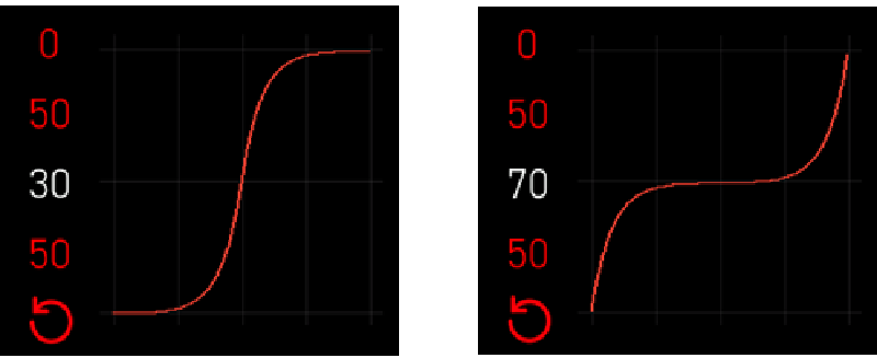
● GLOBAL RATIO : Controls the overall scale ofthe velocity curve.
Higher values increase sensitivity, while lower valuesreduce responsiveness
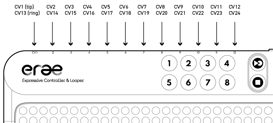
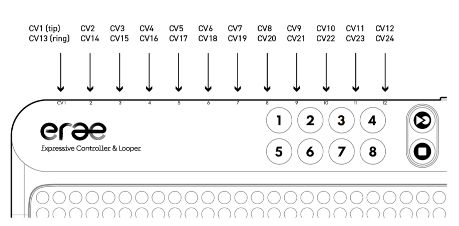
Splitter CV
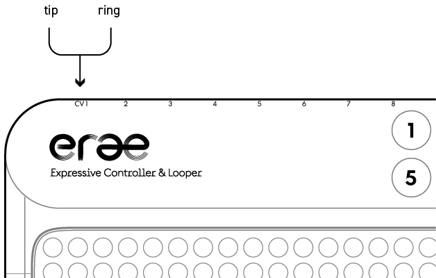
You can configure up to 12 splitters to utilize 24 CV gates, with the tip providing odd outputs and the ring providing even outputs.
FootSw A/B
Once enabled, set footswitch A and/or footswitch B parameters
MIDI Routing
- MIDI → USB Host (abbreviated “Uh”)
- MIDI → Usb Device (abbreviated “Ud”)
- MIDI → MIDI Out A (abbreviated “MID A”)
- MIDI → MIDI Out B (abbreviated “MID B”)
- Usb Device → Usb Host (abbreviated “Ud>Uh”)
- Usb Device → MIDI Out A (abbreviated “Ud>MID A”)
- Usb Device → MIDI Out B (abbreviated “Ud>MID B”)
- Usb Host → Usb Device (abbreviated “Uh>Ud”)
- Usb Host → Usb MIDI A (abbreviated “Uh>MID A”)
- Usb Host → Usb MIDI B (abbreviated “Uh>MID B”)
Save backup Project
A backup project can be overwritten with any project of your choice and saved to the internal memory, not on SD cards, ensuring a secure backup.
Load backup Project
Load your backup project
Load Factory Project
Load the Factory project - cannot be overwritten
Advanced functions
Program Change
In Erae 2, Program Change, Bank Select, MSB, and LSB are used to control and select sounds or patches on a MIDI-compatible device. Buttons and both footswitch A and footswitch B can send Program Change on both states ON (trigger) and OFF (release). You can also latch these two states.
Some jargon about on/off states:
We call BankSel off, MSB off, LSB off and PC off, the Bank Select, MSB, and LSB and Program Change value corresponding to the off-state or release state of the button/footswitch pedal.
Similarly, we call BankSel on, MSB on, LSB on and PC on, the Bank Select, MSB, and LSB and Program Change value corresponding to the on-state or triggered state of the button/footswitch pedal.
Here's what Bank Select, MSB and LSB mean:
Bank Select:
- MIDI allows for 128 program changes (0–127), but some devices offer more than 128 patches or sounds. To access these additional sounds, the Bank Select command is used to switch between different banks of sounds or presets.
- It’s essentially an extension of the Program Change command.
MSB (Most Significant Byte):
- The MSB is part of the Bank Select message and represents the higher-order byte (more significant digits) of the bank number.
- It defines the "coarse" part of the bank, which allows for broader selection across multiple banks.
LSB (Least Significant Byte):
- The LSB is the complementary part of the Bank Select message and represents the lower-order byte (less significant digits) of the bank number.
- It provides finer granularity within the bank selection process.
How They Work Together:
- To select a specific sound, you typically:some text
- Send a Bank Select MSB message.
- Optionally send a Bank Select LSB message.
- Send a Program Change (PC) message to choose the desired patch within the selected bank.
This three-step process ensures you can select from a much larger range of sounds than what a single Program Change message can handle alone. Keep in mind that buttons, footswitch A and footswitch B can handle MSB/LSB/PC for both ON/OFF states.
Example:
If a synthesizer has multiple banks of 128 patches:
- BankSel off MSB 1, LSB 0, Program Change 10 might select patch 10 in bank 1 when a button or footswitch is released
- BankSel on MSB 2, LSB 3, Program Change 50 could select patch 50 in bank 2, sub-bank 3 when a button or footswitch is triggered
These messages are often managed automatically by software or hardware MIDI controllers, but understanding their structure is essential when programming MIDI manually.
Advanced functions
Ableton Live Controller
Windows
Instructions:
- Download and Unzip erae_ableton_script.zip
- Go to C:\ProgramData\Ableton\Live 11 Suite\Resources\MIDI Remote Scripts
- Copy content of folder ableton_scripts into the Midi Remote Scripts folder:
- Erae_2
- Erae_Touch
- Restart Ableton Live
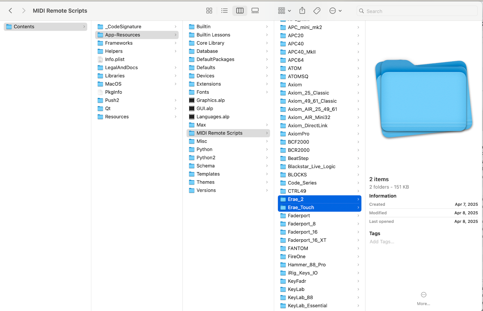
Mac OS
Instructions:
- Download the erae_ableton_script.zip
- Go to Application
- Right click on Live X (11 or 12) -> Show Package Content

- Navigate to Contents -> App-Ressources -> Midi Remote Scripts
- Copy content of folder ableton_scripts into the Midi Remote Scripts folder:
- Erae_2
- Erae_Touch
- Restart Ableton Live
Open Ableton Live:
- Go to Settings -> Midi
- Select Control Surface Erae 2
- Select Input Erae 2 (MIDI) / Output Erae 2 (MIDI)
Usage:
- Create a layout with the LivePad element with the EraeLab for Erae 2 editor
- Open Ableton Live
- Control Ableton with the LivePad
- Hold [MAP] button and drag your finger to move the control surface into Live
Advanced functions
API SysEx
The ERAE API is a custom sysex protocol with messages to:
- Receive finger detections
- Control LED states
Usage:
- Create a layout with a “API zone” element
- Select the API zone index from the setting tab on the right
- Communicate with the your Erae with the API sysex messages
We provide an implementation example in Python: [LINK TO ERAE API V2 PYTHON is coming soon]
External interface
Mapping
The Mapping settings are accessible both on the Erae and on the Lab. They provide access to MIDI parameters such as channel, pitch bend range, and Control Change (CC). These settings allow you to send CC messages to your DAW or synth corresponding to various touch dimensions: absolute X, absolute Y, pressure Z, relative X, and relative Y (all explained in detail). Additionally, it displays the channel number of the active element in the current layout.
How to map a CC
Whether you set the CCs on the Lab or directly on the Erae, you’ll need to map them to your DAW or synth from the Erae. To do this, simply trigger the toggle button corresponding to the CC attribute you wish to map.
For example, if you want to map Pressure to a parameter in your DAW, first ensure your DAW is in mapping mode or learn mode. Then, on your Erae, press the MAP button, scroll down to Pressure, and toggle it on. This will send the CC value assigned to the Pressure CC, which is displayed just below.
If you modify the Pressure CC value, you’ll need to toggle Pressure off and then back on to apply the change. If Pressure is already toggled on but your DAW parameter hasn’t been mapped, simply toggle Pressure off and on again.
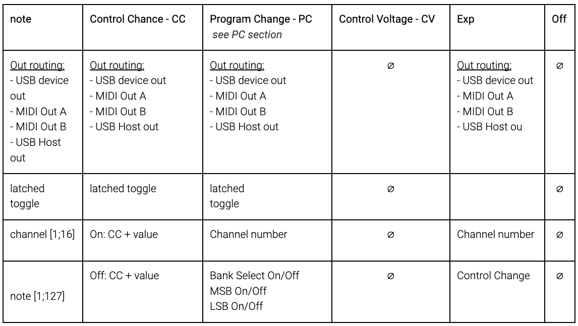
Out routing
Set the "out routing" of your element to your chosen MIDI output I/O
- USB device out: On/Off
- MIDI Out A: On/Off
- MIDI Out B: On/Off
- USB Host out: On/Off
MPE
Set your pitched element in MPE or not
On/Off
Channel
Set your element MIDI channel from 1 to 16, or Channel 1 (low) / Channel 16 (high) if MPE is toggled on
MIDI 1 → [1;16]
MIDI MPE → (Channel 1, 16) - equivalent to Low and High registers
PB Range
Pitch bend range is set to 12 semitones by default when MPE is off and 48 semitones when it’s on
Pressure

On/Off - Pressure is Mapped to a CC to the pressure
X & Y Abs
X abs
Map a CC value to X abs - corresponds to the X-axis (horizontal) position in a cartesian frame of reference where (0) is at the left of the key and (127) on the right. You can set the Min/Max range in the Lab.
Y Abs
Map a CC value to Y abs - corresponds to the Y-axis (vertical) position in a cartesian frame of reference where (0) is at the bottom of the key and (127) at the top right hand corner. You can set the Min/Max range in the Lab.
X & Y Rel

X Rel
Map a CC value to X Rel - corresponds to the relative displacement in the X-axis (horizontal) in a cartesian frame of reference where default value 63 is at the onset touch location. You can set the Initial Value in the Lab as well as the Min/Max range.
Y Rel
Map a CC value to Y Rel - corresponds to the relative displacement in the Y-axis (vertical) position in a cartesian frame of reference where default value 63 is at the onset touch location. You can set the Initial Value in the Lab as well as the Min/Max range. Within the Mapping settings, you can find MIDI parameters such as channel, Pitchbend range, Control Change (CC). The main purpose is to send your DAW or synth the control change (CC) corresponding to the different touch dimensions : abs X , abs Y , pressure Z , rel X and rel Y (all explained . It also displays the channel number from the active element on the current layout.
External interface
Control Voltage - CV/gate
Erae2 has a whopping 24 analog outputs for all your CV needs. Each of the 12 dual jack output can either be used directly or with a dual splitter.
The voltage range of -5/+8V will cover all you need to take control of your modular rig : 1V/oct, triggers, unipolar and bipolar modulation, and more in the future!
The CV outputs are easily configurable via Erae lab, we will cover all settings for every element in this chapter.
Overlapping routings issue: 🚩
Note that we did not restrict the use of outputs to just one element, meaning that one output can be used on 2 different layouts, which could create conflicts if for example you record a loop on one layout and play the other simultaneously. The Erae Lab will warn you when there are conflicts in the routing, but won’t prevent you from doing it !
Control Voltage attributes
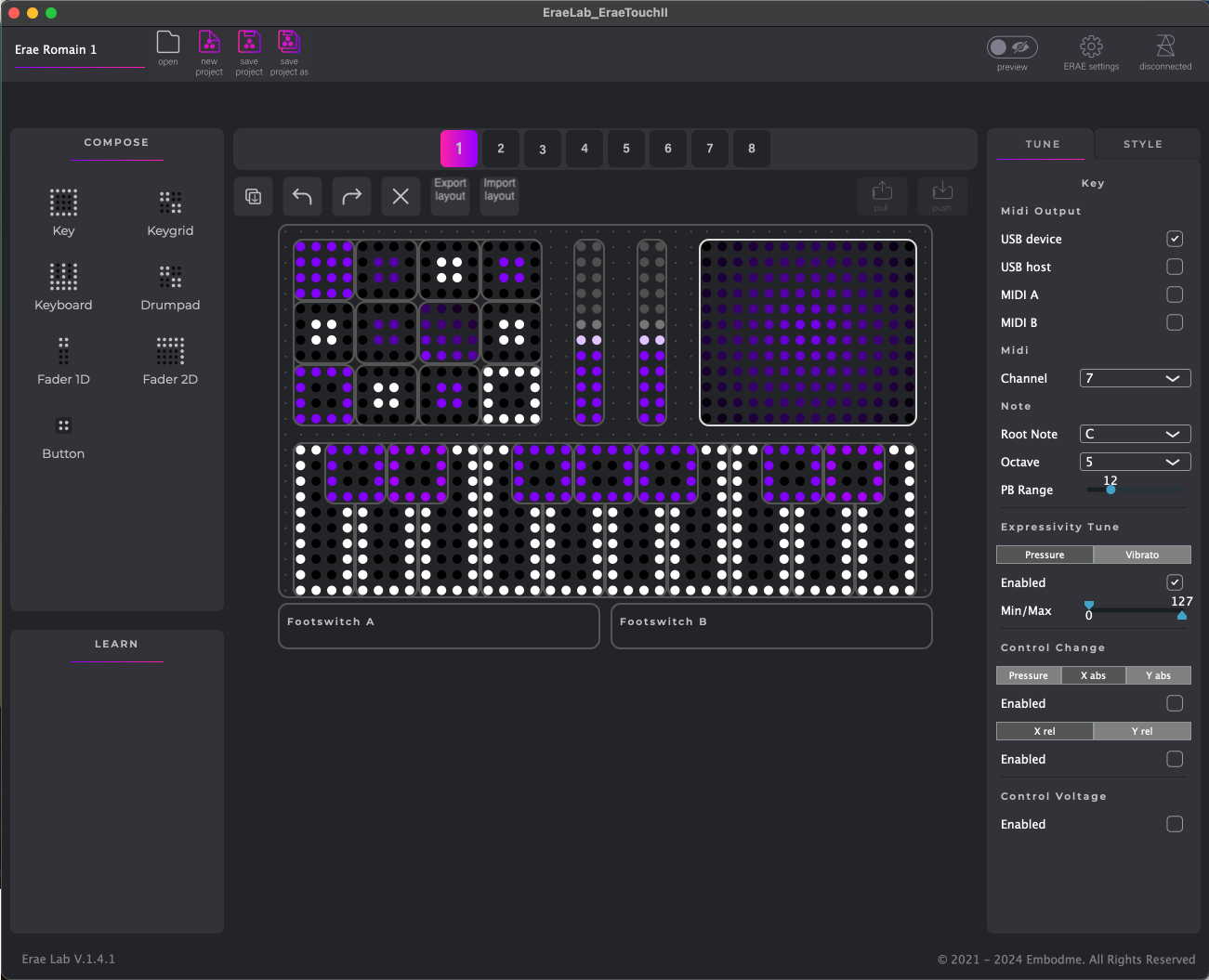
The control change attributes in the Lab's TUNE section are listed at the bottom as following:
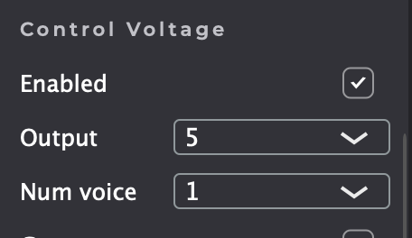
- Enabled [on/off]
You can enable or disable CV in the selected element - Output [1-24]
Corresponds to the physical CV output number where you want the CV attribute list to start (more on this in the “Ordering of voices with physical outputs “ section) - Num Voice
Corresponds to the number of attributes (eg. gate, pitch, etc.) per note or voice.
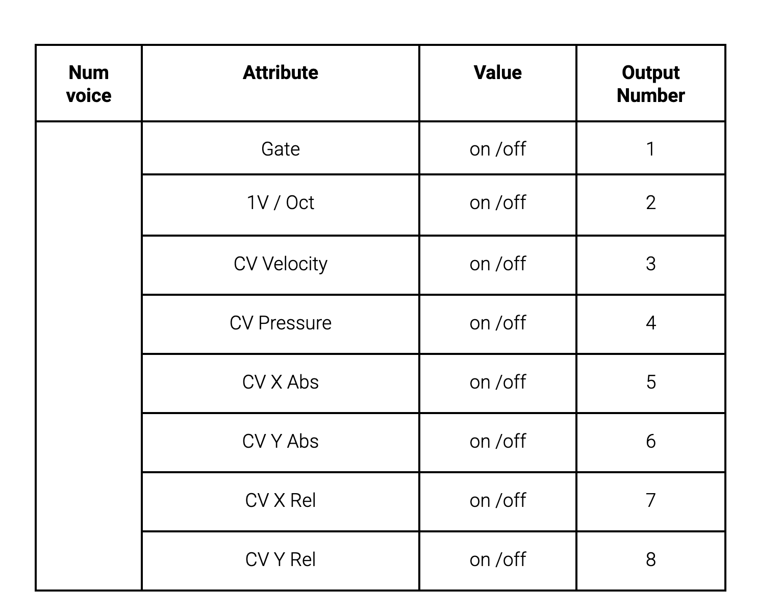
Let’s dive in the Num Voice attributes. For each note, you can set up to 8 attributes, listed as below.
Voice number principle
For each CV attribute active in the Lab/Tune/CV section, you need one physical CV output
If you want to play CV modulars with polyphony, you will need to use several notes we call voices. As seen above, each voice is comprised of 1 or several (up to 8) attributes (eg. gate, pitch, pressure, etc.). Each voice will require the same number of outputs required for the number of attributes you enable. For instance, if you enable 4 attributes (eg. gate, 1V/oct, velocity and pressure), you will require 4 outputs per voice.
Ordering of voices with physical outputs
The principle is simple: one voice requires x outputs (1 to 8). All available physical outputs will be grouped by the number of enabled attributes. Setting the voice number means repeating this set of enabled attributes several times. One set of attributes/outputs per voice, up to the desired (and available) number.
Eg. With 24 outputs available, you can play up to 6 notes/voices (4x6=24).
Single mode (no splitter used)
The output attribute corresponds to the number where the physical outputs start. If you need two attributes for a button (eg. Gate & 1V / Oct) and have the Output attribute: 5, then it means CV data is streamed as follow. 5: Gate, 6: 1V / Oct
Dual mode (splitter used)
When using splitter cables, each physical CV output is effectively doubled. The same principles outlined earlier still apply, but the ordering is adjusted as follows.
Keyboards, Key, Keygrids and Drumpads
- Enable : enable/disable CV output for the selected element
- Output : Select the first hardware output. Each enabled output of the following section will be assigned sequentially in the order they appear here.
- Num voice : Select number of voices for polyphony. Each voice will use the same amount of CV with every enabled parameter, so to know how many outputs you need, multiply the number of enabled CV outputs by the number of voices.
- Gate : Toggle 5V gate
- 1 V/Oct : Toggle 1V/Octave
- CV Velocity : Toggle velocity. When enabled, you can select the voltage range of the output.
- CV Pressure : Toggle pressure. When enabled, you can select the voltage range of the output.
- CV X abs : Toggle X absolute modulation, or absolute horizontal modulation. On each key, the lowest value is the left-most position, and the highest value is the right-most position. When enabled, you can select the voltage range of the output.
- CV Y abs : Toggle Y absolute modulation, or absolute vertical modulation On each key, the lowest value is the bottom position, and the highest value is the top position. When enabled, you can select the voltage range of the output.
- CV X rel : Toggle X relative modulation, or relative horizontal modulation. On each key, the lowest value is the left-most position, and the highest value is the right-most position. You can set an initial value and a range. The initial value is set on the initial strike position of your finger.
- CV Y rel : Toggle Y relative modulation, or relative vertical modulation. On each key, the lowest value is the bottom position, and the highest value is the top position. You can set an initial value and a range. The initial value is set on the initial strike position of your finger.
Fader 1D
- Pressure : Toggle CV pressure for that fader. Once enabled, you can select output and range
- Y Abs : Toggle the fader’s vertical axis CV output, select output and range. Once enabled, you can select output and range.
Fader 2D
- Pressure : Toggle CV pressure for that fader. Once enabled, you can select output and range
- X Abs : Toggle the fader’s horizontal axis CV output, select output and range. Once enabled, you can select output and range.
- Y Abs : Toggle the fader’s vertical axis CV output, select output and range. Once enabled, you can select output and range.
Note Button
- Enable : Toggle one or off
- Output : Select the first hardware output. Each enabled output of the following section will be assigned sequentially in the order they appear here.
- Gate : Toggle 5V gate
- 1 V/oct : Toggle 1V/Octave
Control Voltage Button
- Latched : Enable button’s latching
- Output : Set the button’s hardware output
- On/Off : Select the On and Off value for the button (Off value is the buttom value, On value is the top value).
CV Calibration
Instructions:
● Unplug all CV TRS jacks andFootswitch pedal
● Start Erae2 with external powersupply
● Go to [SETTINGS] menu and selectRun CV calibration
The calibration process will take about 5 to10 minutes and the Erae2 will reboot automatically after the calibration.
Once the calibration is complete, it ispossible to also adjust the calibration gain (scaling factor) manually:
● Go to [SETTINGS] menu
● Change the CV gain (cent / octave)
External interface
Footswitch/expression pedal (11-12 ins)
The two rightmost jack outputs (11 and 12) can be configured as expression or switch pedal input. You can enable and configure it in the global settings. The Erae can handle both footswitch (On/Off) and expression (potentiometer) pedal with continuous output.
For the footswitch pedal (with On/Off actions), you should configure the pedal as a button or a note, you have the same configuration options as a button element.
For the expression pedal, the continuous value can be freely assigned to any MIDI CC output.
Erae Lab
Introduction
The Lab is your space to customize your Erae 2 and handle your projects. From one single view, you can access all your projects stored in the computer and in Erae 2’s memory, create layouts from scratch or from a previously created one, and tune the elements. Each section is explained in the Learn panel based on where your mouse is hovering. However, here’s a zone-by-zone breakdown of what you can do to customize your product.
Erae Lab
Lab workflow
When you open the Lab, a blank layout appears, ready for you to begin composing in the Compose tab. To design your layout, simply drag and drop elements from the Compose pane into the central workspace. Each project can include up to 8 layouts, which can be saved together as an .erproj file. Additionally, individual layouts can be exported as .emk files, allowing you to easily manage and organize them across various projects.
Loading projects from your computer
To load an existing project, click the open button. A pop-up window will appear, allowing you to select a file from your computer. Once loaded, the project's 8 layouts will be imported, with the first layout displayed by default.
Loading and saving projects from your Erae
Use the Settings button and LCD menu to load one of your 8 available projects. Similarly, save a project to one of the 8 slots via the Settings button and LCD menu. Be sure to save any modifications made to the current project (e.g., changes to scales on layouts, MPE settings, or added looper patterns) to retain them after a reboot.
Push projects from the Lab to the Erae
To organize projects within the Erae 2, you need to assign them to the correct slots (e.g., project_1, project_2, ... project_8). For example, if you've created a project from scratch in the Lab and want to save it to slot 2, first load project 2 on the Erae through its settings. Then, in the Lab, click the "To the Erae" button to transfer your project.
Load projects from the Erae to the Lab
To load a project onto the Erae, go to Settings → Load, then press the "From the Erae" button in the Lab. The entire project will load, with the first layout displayed by default.
Erae Lab
Tune
Each layout element can be customized in the Lab with options like MIDI channel settings, velocity curves, control change values, colors, sizes, and more. The Tune feature provides another way to adjust element settings, offering flexibility to work even when you're away from your Erae. For example, scales can be pre-configured in the Lab but are also editable directly on the Erae 2 with a single click. Similarly, control changes can be set in the Lab or mapped directly from the pad on the Erae. Keep in mind that scale changes apply only to the currently displayed layout, and if multiple elements are present in a layout, the change will affect the most recently touched element.
Tune Keyboards and Keygrids
Keygrids draw inspiration from string instruments and can be made isomorphic by setting any scale to chromatic. To enable or disable MPE mode on Keygrid or Keyboard elements, toggle the MPE selector under the Tune tab.
In both MIDI 1.0 and MPE modes, the Tune tab focuses on two main aspects: Note and Expressivity attributes.
- Note attributes define settings like scales, pitch bend ranges, and MIDI channels.
- Expressivity attributes control gesture-based parameters such as finger X-Z positions, X-Y relative movements, and advanced pressure options.
This setup ensures a high level of customization for expressive and versatile performance.
Erae Lab
Style
Use the Style panel on the right side of the Lab to personalize the appearance of your elements. Each element has an intuitive customization process, enabling you to design a controller that truly stands out—whether you're using it at home or performing on stage. We’re excited to see your creations!